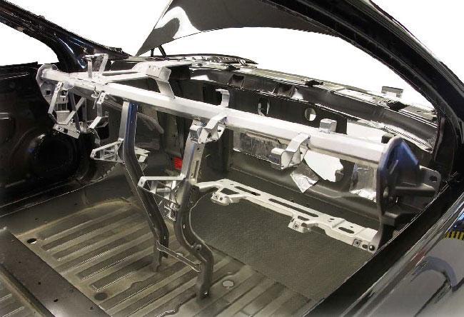
Support Structure
Because its functions include safety, structural support of the instrument panel, and customer metrics driven by noise & vibration (NVH), the cross car beam is essential. Depending on the source, the cross car beam makes up 20-30% of the instrument panel weight, yet it is behind the scenes, never seen by the customer.
Beam Design
The cross car beam design does not change between internal combustion engine (ICE) vehicles and electric vehicles. The design cues may be different between the ICE and EVs as many EVs use a large screen in lieu of buttons and knobs, while the attachment points, steering wheel support, and airbag mounts are the same. The design and materials create a value proposition that includes weight, cost, customer appreciation, safety, prototype, and production tooling, and the ability to make changes within the program development.
Areas of Focus
The cross car beam is the backbone of the instrument panel. From a structural perspective, the ends are mounted to the body walls and the firewall. This means there needs to be ample structural support for the steering column for both safety and driver comfort.
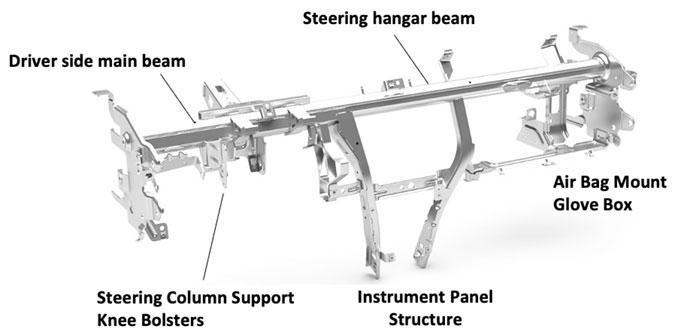
Vibration control is a major element in the design of the cross car beam. If the steering column shakes, we associate it with a steering or a brake issue. That is, if the cross car beam is not flexing. Likewise, if the display screen on the dash or the center console is vibrating, customers would perceive the vehicle to be low quality. The major areas of focus on a cross-car beam are identified here:
- Drive side main beam
- Steering column support knee bolsters
- Steering hanger beam
- Instrument panel structure
- Airbag mount glove box
Producing Car Beams
There are multiple methods and materials utilized to produce cross car beams. The baseline is a steel fabrication made of tube and plate, which offers the lowest cost and the highest stiffness option, yet is also the heaviest and the assembly fixturing is expensive. As vehicle lightweighting increases in importance, other methods to produce cross car beams are growing in popularity. One is a fabrication of aluminum extrusions, while another is a multi-material option using a mix of materials.
A third solution is a magnesium die casting which provides the lowest weight, yet it is also lowest in stiffness, which may negatively affect NVH metrics, namely vibration. Another program hurdle the magnesium die castings face is in the significant tooling investment, which can be costly, especially for the low-volume EV programs.

Design with Extrusions
Cross car beams are subject to twisting loads from road loads, so it is advantageous to use hollow structures that naturally provide torsional stiffness. Aluminum extrusions have a clear advantage in weight-sensitive designs because it is a low-density, easy to fabricate, and readily available material.
The Cadillac CTS program optimized a magnesium design with extrusions and cut 36% of the weight. The 6000 series alloys are common, namely the easy-to-extrude 6063, and stronger 6061 and 6005A when required in localized areas.

Alloy Selection
Alloy selection varies for product performance and manufacturing requirements. For example, 6005A is sometimes selected over 6061 or 6082 in the main tube because there is less distortion due to quench rates, and with welding, which reduces tolerance stack-up in assembly.
Of course, these areas of concern can also utilize the temper that is best suited to strength, toughness, and product performance.
The benefit of using 6000 series alloys throughout is that they can all be easily joined using traditional aluminum welding, adhesives, and other joining techniques.
Assembly features like datums are easy to incorporate for installation and assembly.

Why Are Extrusions Well-Suited for Cross Car Beam Design?
Extrusions deliver an efficient geometry offering multiple functions & benefits:
- Lightweighting
- Stiffness for structural mounts & NVH
- Tight-tolerance sections over long lengths
- Ease of assembly & integration
- Value & optimization through geometry
- Versatile & Innovative Integration


The designs shown here are difficult in die casting because the X and Y dimensions of the mold get extremely thick, resulting in a heavier mold. In turn, the mold is more expensive and requires more thermal mass to manage through the process. In addition, the length (Z) further drives the need for a long, heavy mold.
The typical cross-car beam program requires many molds, so the costs add up and the lead times grow. A die-cast beam tooling may cost $6 million whereas the extrusion tooling on the Acura was under $140,000. It is incredibly cost-effective to implement this geometry with extrusions, within compressed timelines.

Versatile Shapes & Wall Thicknesses
Casting designers like to use consistent wall thickness to maximize material properties. With extrusion-based cross car beams, the integration process is made easier. Designers can use their imaginations for wall thickness and geometry and can utilize metal where required for product performance (value and optimization).
In addition, the extrusion process allows versatile shapes to provide localized strength and stiffness as needed.
Ready to get started? Find an extruder